Gas lift
It has been suggested that this article be merged with airlift pump. (Discuss) Proposed since August 2018. |
Gas lift or bubble pumps use the artificial lift technique of raising a fluid such as water or oil by introducing bubbles of compressed air, water vapor or other vaporous bubbles into the outlet tube. This has the effect of reducing the hydrostatic pressure in the outlet tube vs. the hydrostatic pressure at the inlet side of the tube.
Devices using this type of lift mechanism:
Coffee percolators use vaporized water to lift hot water
Airlift pumps uses compressed air to lift water
Pulser pumps use a subterranean chamber of air for an airlift pump
Suction dredges use an airlift pump to vacuum mud, sand and debris
Mist lift pumps uses vaporized water to lift seawater in Ocean thermal energy conversion
Contents
1 Petroleum industry uses
2 History
3 See also
4 References
5 External links
Petroleum industry uses
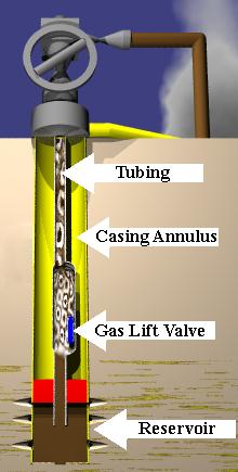
In the United States, gas lift is used in 10% of the oil wells that have insufficient reservoir pressure to produce the well. In the petroleum industry, the process involves injecting gas through the tubing-casing annulus. Injected gas aerates the fluid to reduce its density; the formation pressure is then able to lift the oil column and forces the fluid out of the wellbore. Gas may be injected continuously or intermittently, depending on the producing characteristics of the well and the arrangement of the gas-lift equipment.[1]

The amount of gas to be injected to maximize oil production varies based on well conditions and geometries. Too much or too little injected gas will result in less than maximum production. Generally, the optimal amount of injected gas is determined by well tests, where the rate of injection is varied and liquid production (oil and perhaps water) is measured.
Although the gas is recovered from the oil at a later separation stage, the process requires energy to drive a compressor to raise the pressure of the gas to a level where it can be re-injected.
The gas-lift mandrel is a device installed in the tubing string of a gas-lift well onto which or into which a gas-lift valve is fitted. There are two common types of mandrels. In a conventional gas-lift mandrel, a gas-lift valve is installed as the tubing is placed in the well. Thus, to replace or repair the valve, the tubing string must be pulled. In the side-pocket mandrel, however, the valve is installed and removed by wireline while the mandrel is still in the well, eliminating the need to pull the tubing to repair or replace the valve.
A gas-lift valve is a device installed on (or in) a gas-lift mandrel, which in turn is put on the production tubing of a gas-lift well. Tubing and casing pressures cause the valve to open and close, thus allowing gas to be injected into the fluid in the tubing to cause the fluid to rise to the surface. In the lexicon of the industry, gas-lift mandrels are said to be "tubing retrievable" wherein they are deployed and retrieved attached to the production tubing. See gas-lift mandrel.
Gas lift operation can be optimized in different ways.The newest way is using risk-optimization which considers all aspects for gas lift allocation.
History
Air lift uses compressed air to lift water in operations such as dredging and underwater archeology. It is also found in aquariums to keep water circulating. These forms of lift were used as far back as 1797 in mines to lift water from mine shafts. These systems used single point injection of air into the liquid stream, normally through a foot valve at the bottom of the string. Gas lift was used as early as 1864 in Pennsylvania to lift oil wells, also using compressed air, via an air pipe bringing the air to the bottom of the well. Air was used in Texas for large-scale artificial lift. In 1920 natural gas replaced air, lowering the risk of explosion. From 1929 until 1945 about 25000 patents were issued on different types of gas lift valves that could be used for unloading in stages.[2] Some of these systems involved moving the tubing, or using wireline sinker bars to change the lift point. Others were spring operated valves. Ultimately, in 1944 W.R. King patented the pressurized bellows valve that is used today. In 1951 the sidepocket mandrel was developed for selectively positioning and retrieving gas lift valves with wireline.
See also
- Pumpjack
- Progressive cavity pump
- Submersible pump
References
^ How Does Artificial Lift Work?, Rigzone, retrieved May 29, 2012.mw-parser-output cite.citationfont-style:inherit.mw-parser-output .citation qquotes:"""""""'""'".mw-parser-output .citation .cs1-lock-free abackground:url("//upload.wikimedia.org/wikipedia/commons/thumb/6/65/Lock-green.svg/9px-Lock-green.svg.png")no-repeat;background-position:right .1em center.mw-parser-output .citation .cs1-lock-limited a,.mw-parser-output .citation .cs1-lock-registration abackground:url("//upload.wikimedia.org/wikipedia/commons/thumb/d/d6/Lock-gray-alt-2.svg/9px-Lock-gray-alt-2.svg.png")no-repeat;background-position:right .1em center.mw-parser-output .citation .cs1-lock-subscription abackground:url("//upload.wikimedia.org/wikipedia/commons/thumb/a/aa/Lock-red-alt-2.svg/9px-Lock-red-alt-2.svg.png")no-repeat;background-position:right .1em center.mw-parser-output .cs1-subscription,.mw-parser-output .cs1-registrationcolor:#555.mw-parser-output .cs1-subscription span,.mw-parser-output .cs1-registration spanborder-bottom:1px dotted;cursor:help.mw-parser-output .cs1-ws-icon abackground:url("//upload.wikimedia.org/wikipedia/commons/thumb/4/4c/Wikisource-logo.svg/12px-Wikisource-logo.svg.png")no-repeat;background-position:right .1em center.mw-parser-output code.cs1-codecolor:inherit;background:inherit;border:inherit;padding:inherit.mw-parser-output .cs1-hidden-errordisplay:none;font-size:100%.mw-parser-output .cs1-visible-errorfont-size:100%.mw-parser-output .cs1-maintdisplay:none;color:#33aa33;margin-left:0.3em.mw-parser-output .cs1-subscription,.mw-parser-output .cs1-registration,.mw-parser-output .cs1-formatfont-size:95%.mw-parser-output .cs1-kern-left,.mw-parser-output .cs1-kern-wl-leftpadding-left:0.2em.mw-parser-output .cs1-kern-right,.mw-parser-output .cs1-kern-wl-rightpadding-right:0.2em
^ Gas lift, retrieved 2015-10-14
External links
- Kermit Brown. The Technology of Artificial Lift Methods, vol 2A. The Petroleum Publishing Company, 1980.
- “Subsurface Equipment/Artificial Lift: Maximizing Production from the Well”, May 1999 JPT
- Video showing a bubble pump in action