Pelton wheel

Old Pelton wheel from Walchensee Hydroelectric Power Station, Germany.

Assembly of a Pelton wheel at Walchensee Hydroelectric Power Station, Germany.

Figure from Pelton's original patent (October 1880).
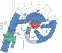
Sectional view of a Pelton turbine installation.

Bucket detail on a small turbine.
A Pelton wheel is an impulse-type water turbine. It was invented by Lester Allan Pelton in the 1870s.[1][2] The Pelton wheel extracts energy from the impulse of moving water, as opposed to water's dead weight like the traditional overshot water wheel. Many variations of impulse turbines existed prior to Pelton's design, but they were less efficient than Pelton's design. Water leaving those wheels typically still had high speed, carrying away much of the dynamic energy brought to the wheels. Pelton's paddle geometry was designed so that when the rim ran at half the speed of the water jet, the water left the wheel with very little speed; thus his design extracted almost all of the water's impulse energy—which allowed for a very efficient turbine.
Contents
1 History
2 Function
3 Applications
4 Design rules
5 Turbine physics and derivation
5.1 Energy and initial jet velocity
5.2 Final jet velocity
5.3 Optimal wheel speed
5.4 Torque
5.5 Power
5.6 Efficiency
6 System components
7 See also
8 References
9 External links
History
Lester Allan Pelton was born in Vermillion, Ohio in 1829. In 1850, he travelled overland to California, to take part in the Gold Rush. Pelton worked by selling fish he caught in the Sacramento River.[3] In 1860, he moved to Camptonville, a center of placer mining activity. At this time many mining operations were powered by steam engines which consumed vast amounts of wood as their fuel. Some water wheels were used in the larger rivers, but they were ineffective in the smaller streams that were found near the mines. Pelton worked on a design for a water wheel that would work with the relatively small flow found in these streams.[4]
By the mid 1870's, Pelton had developed a wooden prototype of his new wheel. In 1876, approached the Miners Foundry in Nevada City to build the first commercial models in iron. The first Pelton Wheel was installed at the Mayflower Mine in Nevada City in 1878.[4]. The efficiency advantages of Pelton's invention were quickly recognized and his product was soon in high demand. By the mid-1880s, the Miners Foundry could not meet the demand, and in 1888, Pelton sold the rights to his name and the patents to his invention to the Pelton Water Wheel Company in San Francisco. The company established a factory at 121/123 Main Street in San Francisco.[5]
The Pelton Water Wheel Company manufactured a large number of Pelton Wheels in San Francisco which were shipped around the world. In 1892, the Company added a branch on the east coast at 143 Liberty Street in New York City. By 1900, over 11,000 turbines were in use. In 1914, the company moved manufacturing to new, larger premises at 612 Alabama Street in San Francisco. In 1956, the company was acquired by the Baldwin-Lima-Hamilton Company, which ended manufacture of Pelton Wheels.[5]
Function
Nozzles direct forceful, high-speed streams of water against a series of spoon-shaped buckets, also known as impulse blades, which are mounted around the outer rim of a drive wheel—also called a runner (see photo, 'Old Pelton wheel..'). As the water jet hits the blades, the direction of water velocity is changed to follow the contours of the blades. The impulse energy of the water jet exerts torque on the bucket-and-wheel system, spinning the wheel; the water jet does a "u-turn" and exits at the outer sides of the bucket, decelerated to a low velocity. In the process, the water jet's momentum is transferred to the wheel and hence to a turbine. Thus, "impulse" energy does work on the turbine. Maximum power and efficiency are achieved when the velocity of the water jet is twice the velocity of the rotating buckets. A very small percentage of the water jet's original kinetic energy will remain in the water, which causes the bucket to be emptied at the same rate it is filled, and thereby allows the high-pressure input flow to continue uninterrupted and without waste of energy. Typically two buckets are mounted side-by-side on the wheel, with the water jet split into two equal streams; this balances the side-load forces on the wheel and helps to ensure smooth, efficient transfer of momentum from the water jet to the turbine wheel.
Because water is nearly incompressible, almost all of the available energy is extracted in the first stage of the hydraulic turbine. Therefore, Pelton wheels have only one turbine stage, unlike gas turbines that operate with compressible fluid.[citation needed]
Applications
Pelton wheels are the preferred turbine for hydro-power where the available water source has relatively high hydraulic head at low flow rates. Pelton wheels are made in all sizes. There exist multi-ton Pelton wheels mounted on vertical oil pad bearings in hydroelectric plants. The largest units - the Bieudron Hydroelectric Power Station at the Grande Dixence Dam complex in Switzerland - are over 400 megawatts [1]. The smallest Pelton wheels are only a few inches across, and can be used to tap power from mountain streams having flows of a few gallons per minute. Some of these systems use household plumbing fixtures for water delivery. These small units are recommended for use with 30 metres (100 ft) or more of head, in order to generate significant power levels. Depending on water flow and design, Pelton wheels operate best with heads from 15–1,800 metres (50–5,910 ft), although there is no theoretical limit.
Design rules
The specific speed ηsdisplaystyle eta _s
Compared to other turbine designs, the relatively low specific speed of the Pelton wheel, implies that the geometry is inherently a "low gear" design. Thus it is most suitable to being fed by a hydro source with a low ratio of flow to pressure, (meaning relatively low flow and/or relatively high pressure).
The specific speed is the main criterion for matching a specific hydro-electric site with the optimal turbine type. It also allows a new turbine design to be scaled from an existing design of known performance.
ηs=nP/ρ(gH)5/4displaystyle eta _s=nsqrt P/sqrt rho (gH)^5/4
where:
ndisplaystyle n= Frequency of rotation (rpm)
Pdisplaystyle P= Power (W)
Hdisplaystyle H= Water head (m)
ρdisplaystyle rho= Density (kg/m3)
The formula implies that the Pelton turbine is geared most suitably for applications with relatively high hydraulic head H, due to the 5/4 exponent being greater than unity, and given the characteristically low specific speed of the Pelton.[7]
Turbine physics and derivation
Energy and initial jet velocity
In the ideal (frictionless) case, all of the hydraulic potential energy (Ep = mgh) is converted into kinetic energy (Ek = mv2/2) (see Bernoulli's principle). Equating these two equations and solving for the initial jet velocity (Vi) indicates that the theoretical (maximum) jet velocity is Vi = √2gh. For simplicity, assume that all of the velocity vectors are parallel to each other. Defining the velocity of the wheel runner as: (u), then as the jet approaches the runner, the initial jet velocity relative to the runner is: (Vi − u).[7]
The initial velocity of jet is Vi
Final jet velocity
Assuming that the jet velocity is higher than the runner velocity, if the water is not to become backed-up in runner, then due to conservation of mass, the mass entering the runner must equal the mass leaving the runner. The fluid is assumed to be incompressible (an accurate assumption for most liquids). Also it is assumed that the cross-sectional area of the jet is constant. The jet speed remains constant relative to the runner. So as the jet recedes from the runner, the jet velocity relative to the runner is: −(Vi − u) = −Vi + u. In the standard reference frame (relative to the earth), the final velocity is then: Vf = (−Vi + u) + u = −Vi + 2u.
Optimal wheel speed
We know that the ideal runner speed will cause all of the kinetic energy in the jet to be transferred to the wheel. In this case the final jet velocity must be zero. If we let −Vi + 2u = 0, then the optimal runner speed will be u = Vi /2, or half the initial jet velocity.
Torque
By Newton's second and third laws, the force F imposed by the jet on the runner is equal but opposite to the rate of momentum change of the fluid, so
F = −m(Vf − Vi)/t = −ρQ[(−Vi + 2u) − Vi] = −ρQ(−2Vi + 2u) = 2ρQ(Vi − u),
where ρ is the density, and Q is the volume rate of flow of fluid. If D is the wheel diameter, the torque on the runner is
T = F(D/2) = ρQD(Vi − u).
The torque is maximal when the runner is stopped (i.e. when u = 0, T = ρQDVi). When the speed of the runner is equal to the initial jet velocity, the torque is zero (i.e. when u = Vi, then T = 0). On a plot of torque versus runner speed, the torque curve is straight between these two points: (0, pQDVi) and (Vi, 0).[7]
Nozzle efficiency is the ratio of the jet power to the water power at the base of nozzle
Power
The power P = Fu = Tω, where ω is the angular velocity of the wheel. Substituting for F, we have P = 2ρQ(Vi − u)u. To find the runner speed at maximum power, take the derivative of P with respect to u and set it equal to zero, [dP/du = 2ρQ(Vi − 2u)]. Maximum power occurs when u = Vi /2. Pmax = ρQVi2/2. Substituting the initial jet power Vi = √2gh, this simplifies to Pmax = ρghQ. This quantity exactly equals the kinetic power of the jet, so in this ideal case, the efficiency is 100%, since all the energy in the jet is converted to shaft output.[7]
Efficiency
A wheel power divided by the initial jet power, is the turbine efficiency, η = 4u(Vi − u)/Vi2. It is zero for u = 0 and for u = Vi. As the equations indicate, when a real Pelton wheel is working close to maximum efficiency, the fluid flows off the wheel with very little residual velocity.[7] In theory, the energy efficiency varies only with the efficiency of the nozzle and wheel, and does not vary with hydraulic head.[8]
The term "efficiency" can refer to: Hydraulic, Mechanical, Volumetric, Wheel, or overall efficiency.
System components
The conduit bringing high-pressure water to the impulse wheel is called the penstock. Originally the penstock was the name of the valve, but the term has been extended to include all of the fluid supply hydraulics. Penstock is now used as a general term for a water passage and control that is under pressure, whether it supplies an impulse turbine or not.[7]
See also
- Peltric set
- Centrifugal pump
References
^ "COW THAT ASSISTED SCIENCE". The South Eastern Times. , (1661). South Australia. 24 November 1922. p. 6. Retrieved 10 March 2017 – via National Library of Australia..mw-parser-output cite.citationfont-style:inherit.mw-parser-output qquotes:"""""""'""'".mw-parser-output code.cs1-codecolor:inherit;background:inherit;border:inherit;padding:inherit.mw-parser-output .cs1-lock-free abackground:url("//upload.wikimedia.org/wikipedia/commons/thumb/6/65/Lock-green.svg/9px-Lock-green.svg.png")no-repeat;background-position:right .1em center.mw-parser-output .cs1-lock-limited a,.mw-parser-output .cs1-lock-registration abackground:url("//upload.wikimedia.org/wikipedia/commons/thumb/d/d6/Lock-gray-alt-2.svg/9px-Lock-gray-alt-2.svg.png")no-repeat;background-position:right .1em center.mw-parser-output .cs1-lock-subscription abackground:url("//upload.wikimedia.org/wikipedia/commons/thumb/a/aa/Lock-red-alt-2.svg/9px-Lock-red-alt-2.svg.png")no-repeat;background-position:right .1em center.mw-parser-output .cs1-subscription,.mw-parser-output .cs1-registrationcolor:#555.mw-parser-output .cs1-subscription span,.mw-parser-output .cs1-registration spanborder-bottom:1px dotted;cursor:help.mw-parser-output .cs1-hidden-errordisplay:none;font-size:100%.mw-parser-output .cs1-visible-errorfont-size:100%.mw-parser-output .cs1-subscription,.mw-parser-output .cs1-registration,.mw-parser-output .cs1-formatfont-size:95%.mw-parser-output .cs1-kern-left,.mw-parser-output .cs1-kern-wl-leftpadding-left:0.2em.mw-parser-output .cs1-kern-right,.mw-parser-output .cs1-kern-wl-rightpadding-right:0.2em
^ "MINING INTELLIGENCE". Launceston Examiner. XLV, (210). Tasmania, Australia. 22 August 1885. p. 3. Retrieved 10 March 2017 – via National Library of Australia.
^ Lescohier, Roger P. (2011). Lester Pelton and the Pelton Water Wheel. Nevada County Historical Society. ISBN 978-0-915641-15-4.
^ ab "Lester Allan Pelton". American Society of Mechanical Engineers.
^ ab "Showplace Square Historic Resource Survey Findings" (PDF). San Francisco Planning Department. 2012.
^ Sayers, A. T. (1990). Hydraulic and Compressible Flow Turbomachines. Mcgraw Hill Book Co Ltd. ISBN 978-0-07-707219-3.
^ abcdef Technical derivation of basic impulse turbine physics, by J.Calvert
^ Pelton Wheel Water Turbine, Ron Amberger's Pages
External links
| Wikimedia Commons has media related to Pelton wheel. |
- Example Hydro at Dorado Vista ranch
Hydropower | ||
|---|---|---|
Hydroelectricity generation |
|  |
Hydroelectricity equipment |
| |


