Deformation (engineering)

Compressive stress results in deformation which shortens the object but also expands it outwards.
In materials science, deformation refers to any changes in the shape or size of an object due to
- an applied force (the deformation energy in this case is transferred through work) or
- a change in temperature (the deformation energy in this case is transferred through heat).
The first case can be a result of tensile (pulling) forces, compressive (pushing) forces, shear, bending or torsion (twisting).
In the second case, the most significant factor, which is determined by the temperature, is the mobility of the structural defects such as grain boundaries, point vacancies, line and screw dislocations, stacking faults and twins in both crystalline and non-crystalline solids. The movement or displacement of such mobile defects is thermally activated, and thus limited by the rate of atomic diffusion.[1][2]
Deformation is often described as strain.
The concept of deformation is also linked to the study of the stability of an elastic material by using the method of incremental deformations, based on a superposed small deformation on an equilibrium solution.
As deformation occurs, internal inter-molecular forces arise that oppose the applied force. If the applied force is not too great, these forces may be sufficient to completely resist the applied force and allow the object to assume a new equilibrium state and to return to its original state when the load is removed. A larger applied force may lead to a permanent deformation of the object or even to its structural failure.
In the figure it can be seen that the compressive loading (indicated by the arrow) has caused deformation in the cylinder so that the original shape (dashed lines) has changed (deformed) into one with bulging sides. The sides bulge because the material, although strong enough to not crack or otherwise fail, is not strong enough to support the load without change. As a result, the material is forced out laterally. Internal forces (in this case at right angles to the deformation) resist the applied load.
The concept of a rigid body can be applied if the deformation is negligible.
Contents
1 Types of deformation
1.1 Elastic deformation
1.2 True stress and strain
1.3 Plastic deformation
1.3.1 Metal fatigue
1.3.2 Compressive failure
1.4 Fracture
2 Misconceptions
3 See also
4 References
5 External links
Types of deformation
Depending on the type of material, size and geometry of the object, and the forces applied, various types of deformation may result. The image to the right shows the engineering stress vs. strain diagram for a typical ductile material such as steel. Different deformation modes may occur under different conditions, as can be depicted using a deformation mechanism map.
Permanent deformation is irreversible; the deformation stays even after removal of the applied forces, while the temporary deformation is recoverable as it disappears after the removal of applied forces.
Temporary deformation is also called elastic deformation, while the permanent deformation is called plastic deformation.
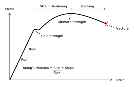
Typical stress vs. strain diagram indicating the various stages of deformation.
Elastic deformation
The study of temporary or elastic deformation in the case of engineering strain is applied to materials used in mechanical and structural engineering, such as concrete and steel, which are subjected to very small deformations. Engineering strain is modeled by infinitesimal strain theory, also called small strain theory, small deformation theory, small displacement theory, or small displacement-gradient theory where strains and rotations are both small.
For some materials, e.g. elastomers and polymers, subjected to large deformations, the engineering definition of strain is not applicable, e.g. typical engineering strains greater than 1%,[3] thus other more complex definitions of strain are required, such as stretch, logarithmic strain, Green strain, and Almansi strain. Elastomers and shape memory metals such as Nitinol exhibit large elastic deformation ranges, as does rubber. However, elasticity is nonlinear in these materials.
Normal metals, ceramics and most crystals show linear elasticity and a smaller elastic range.
Linear elastic deformation is governed by Hooke's law, which states:
- σ=Eεdisplaystyle sigma =Evarepsilon

Where σdisplaystyle sigma 

Note that not all elastic materials undergo linear elastic deformation; some, such as concrete, gray cast iron, and many polymers, respond in a nonlinear fashion. For these materials Hooke's law is inapplicable.[4]
True stress and strain
Since we disregard the change of area during deformation above, the true stress and strain curve should be re-derived. For deriving the stress strain curve, we can assume that the volume change is 0 even if we deformed the materials. We can assume that:
Ai×εi=Af×εfdisplaystyle A_itimes varepsilon _i=A_ftimes varepsilon _f

Then, the true stress can be expressed as below:σT=F/Af=F/Ai×Ai/Af=σe×lf/li=σE×(li+δl)/li=σE(1+εE)displaystyle sigma _T=F/A_f=F/A_itimes A_i/A_f=sigma _etimes l_f/l_i=sigma _Etimes (l_i+delta l)/l_i=sigma _E(1+varepsilon _E)

Additionally, the true strain εT can be express as below:
εT=δl/l0+δl/l1+δl/l2+⋅⋅⋅=Σδl/lidisplaystyle varepsilon _T=delta l/l_0+delta l/l_1+delta l/l_2+cdot cdot cdot =Sigma delta l/l_i

Then, we can express the value as ∫l0lidl/ldx=ln(li/l0)=ln(1+εE)displaystyle int _l_0^l_idl/l,dx=ln(l_i/l_0)=ln(1+varepsilon _E)

Thus, we can induce the plot in terms of σTdisplaystyle sigma _T

Additionally, based on the true stress-strain curve, we can estimate the region where necking starts to happen. Since necking starts to appear after ultimate tensile stress where the maximum force applied, we can express this situation as below:
dF=0=σTdAi+AidσTdisplaystyle dF=0=sigma _TdA_i+A_idsigma _T

so this form can be expressed as below:
dσTσT=−dAiAidisplaystyle frac dsigma _Tsigma _T=-frac dA_iA_i

It indicates that the necking starts to appear where reduction of area becomes much significant compared to the stress change. Then the stress will be localized to specific area where the necking appears.
Additionally, we can induce various relation based on true stress-strain curve.
1) True strain and stress curve can be expressed by the approximate linear relationship by taking a log on true stress and strain. The relation can be expressed as below:
σT=K×(εT)ndisplaystyle sigma _T=Ktimes (varepsilon _T)^n

Where Kdisplaystyle K

2) In reality, stress is also highly dependent on the rate of strain variation. Thus, we can induce the empirical equation based on the strain rate variation.
σT=K′×(εT˙)mdisplaystyle sigma _T=K'times (dot varepsilon _T)^m


True stress-strain curve of FCC metal and its derivative form[5]
Where K′displaystyle K'


By combining the 1) and 2), we can create the ultimate relation as below:
σT=K″×(εT)n(εT˙)mdisplaystyle sigma _T=K''times (varepsilon _T)^n(dot varepsilon _T)^m

Where K″displaystyle K''
3) Based on the true stress-strain curve and its derivative form, we can estimate the strain necessary to start necking. This can be calculated based on the intersection between true stress-strain curve as shown in right.
This figure also shows the dependency of the necking strain at different temperature. In case of FCC metals, both of the stress-strain curve at its derivative are highly dependent on temperature. Therefore, at higher temperature, necking starts to appear even under lower strain value.
All of these properties indicate the importance of calculating the true stress-strain curve for further analyzing the behavior of materials in sudden environment.
4) A graphical method, so-called "Considere construction", can help determine the behavior of stress-strain curve whether necking or drawing happens on the sample. By setting λ=L/L0displaystyle lambda =L/L_0
σT=σe×λ,εT=lnλdisplaystyle sigma _T=sigma _etimes lambda ,varepsilon _T=lnlambda

Therefore, the value of engineering stress can be expressed by the secant line from made by true stress and λdisplaystyle lambda 


Considere Plot. (a) True stress-strain curve without tangents. There is neither necking nor drawing. (b) With one tangent. There is only necking. (c) With two tangents. There are both necking and drawing.[7]
On the figure (a), there is only concave upward Considere plot. It indicates that there is no yield drop so the material will be suffered from fracture before it yields. On the figure (b), there is specific point where the tangent matches with secant line at point where λ=λYdisplaystyle lambda =lambda _Y


Plastic deformation

Swebor-brand high-strength low alloy steel plate, showing both sides, after plastic deformation from defeating projectiles in ballistics testing. Note: When exposed to fire, steel first expands and then loses its strength, exceeding critical temperature at 538°C or 1000°F per ASTM E119 unless treated with fireproofing.
This type of deformation is irreversible. However, an object in the plastic deformation range will first have undergone elastic deformation, which is reversible, so the object will return part way to its original shape. Soft thermoplastics have a rather large plastic deformation range as do ductile metals such as copper, silver, and gold. Steel does, too, but not cast iron. Hard thermosetting plastics, rubber, crystals, and ceramics have minimal plastic deformation ranges. An example of a material with a large plastic deformation range is wet chewing gum, which can be stretched dozens of times its original length.
Under tensile stress, plastic deformation is characterized by a strain hardening region and a necking region and finally, fracture (also called rupture). During strain hardening the material becomes stronger through the movement of atomic dislocations. The necking phase is indicated by a reduction in cross-sectional area of the specimen. Necking begins after the ultimate strength is reached. During necking, the material can no longer withstand the maximum stress and the strain in the specimen rapidly increases. Plastic deformation ends with the fracture of the material.
Metal fatigue
Another deformation mechanism is metal fatigue, which occurs primarily in ductile metals. It was originally thought that a material deformed only within the elastic range returned completely to its original state once the forces were removed. However, faults are introduced at the molecular level with each deformation. After many deformations, cracks will begin to appear, followed soon after by a fracture, with no apparent plastic deformation in between. Depending on the material, shape, and how close to the elastic limit it is deformed, failure may require thousands, millions, billions, or trillions of deformations.
Metal fatigue has been a major cause of aircraft failure, especially before the process was well understood (see, for example, the De Havilland Comet accidents). There are two ways to determine when a part is in danger of metal fatigue; either predict when failure will occur due to the material/force/shape/iteration combination, and replace the vulnerable materials before this occurs, or perform inspections to detect the microscopic cracks and perform replacement once they occur. Selection of materials not likely to suffer from metal fatigue during the life of the product is the best solution, but not always possible. Avoiding shapes with sharp corners limits metal fatigue by reducing stress concentrations, but does not eliminate it.
Analysis of the bulging factor of pressurized parts of the plane can assist in evaluating the damage tolerance of airframe fuselages.[8]

Diagram of a stress–strain curve, showing the relationship between stress (force applied) and strain (deformation) of a ductile metal.
Compressive failure
Usually, compressive stress applied to bars, columns, etc. leads to shortening.
Loading a structural element or specimen will increase the compressive stress until it reaches its compressive strength. According to the properties of the material, failure modes are yielding for materials with ductile behavior (most metals, some soils and plastics) or rupturing for brittle behavior (geomaterials, cast iron, glass, etc.).
In long, slender structural elements — such as columns or truss bars — an increase of compressive force F leads to structural failure due to buckling at lower stress than the compressive strength.
Fracture
This type of deformation is also irreversible. A break occurs after the material has reached the end of the elastic, and then plastic, deformation ranges. At this point forces accumulate until they are sufficient to cause a fracture. All materials will eventually fracture, if sufficient forces are applied.
Misconceptions
A popular misconception is that all materials that bend are "weak" and those that don't are "strong". In reality, many materials that undergo large elastic and plastic deformations, such as steel, are able to absorb stresses that would cause brittle materials, such as glass, with minimal plastic deformation ranges, to break.[9]
See also
- Artificial cranial deformation
- Buff strength
- Creep (deformation)
- Deflection (engineering)
- Deformable body
- Deformation (mechanics)
- Deformation mechanism maps
- Deformation Monitoring
- Deformation retract
- Deformation theory
- Discontinuous Deformation Analysis
- Elastic
- Finite deformation tensors
- Malleability
- Planar deformation features
- Plasticity (physics)
- Poisson's ratio
- Strain tensor
- Strength of materials
- Wood warping
References
^ Davidge, R.W. (1979) Mechanical Behavior of Ceramics, Cambridge Solid State Science Series, Eds. Clarke, D.R., et al.
^ Zarzycki, J. (1991) Glasses and the Vitreous State, Cambridge Solid State Science Series, Eds. Clarke, D.R., et al.
^ Rees, David (2006). Basic Engineering Plasticity: An Introduction with Engineering and Manufacturing Applications. Butterworth-Heinemann. p. 41. ISBN 0-7506-8025-3. Archived from the original on 2017-12-22..mw-parser-output cite.citationfont-style:inherit.mw-parser-output .citation qquotes:"""""""'""'".mw-parser-output .citation .cs1-lock-free abackground:url("//upload.wikimedia.org/wikipedia/commons/thumb/6/65/Lock-green.svg/9px-Lock-green.svg.png")no-repeat;background-position:right .1em center.mw-parser-output .citation .cs1-lock-limited a,.mw-parser-output .citation .cs1-lock-registration abackground:url("//upload.wikimedia.org/wikipedia/commons/thumb/d/d6/Lock-gray-alt-2.svg/9px-Lock-gray-alt-2.svg.png")no-repeat;background-position:right .1em center.mw-parser-output .citation .cs1-lock-subscription abackground:url("//upload.wikimedia.org/wikipedia/commons/thumb/a/aa/Lock-red-alt-2.svg/9px-Lock-red-alt-2.svg.png")no-repeat;background-position:right .1em center.mw-parser-output .cs1-subscription,.mw-parser-output .cs1-registrationcolor:#555.mw-parser-output .cs1-subscription span,.mw-parser-output .cs1-registration spanborder-bottom:1px dotted;cursor:help.mw-parser-output .cs1-ws-icon abackground:url("//upload.wikimedia.org/wikipedia/commons/thumb/4/4c/Wikisource-logo.svg/12px-Wikisource-logo.svg.png")no-repeat;background-position:right .1em center.mw-parser-output code.cs1-codecolor:inherit;background:inherit;border:inherit;padding:inherit.mw-parser-output .cs1-hidden-errordisplay:none;font-size:100%.mw-parser-output .cs1-visible-errorfont-size:100%.mw-parser-output .cs1-maintdisplay:none;color:#33aa33;margin-left:0.3em.mw-parser-output .cs1-subscription,.mw-parser-output .cs1-registration,.mw-parser-output .cs1-formatfont-size:95%.mw-parser-output .cs1-kern-left,.mw-parser-output .cs1-kern-wl-leftpadding-left:0.2em.mw-parser-output .cs1-kern-right,.mw-parser-output .cs1-kern-wl-rightpadding-right:0.2em
^ Callister, William D. (2004) Fundamentals of Materials Science and Engineering, John Wiley and Sons, 2nd ed. p. 184.
ISBN 0-471-66081-7.
^ ab Courtney, Thomas (2000). Mechanical Behavior of Materials. Illinois: Waveland Press. p. 165. ISBN 9780073228242.
^ "True Stress and Strain" (PDF).
^ Roland, David. "STRESS-STRAIN CURVES" (PDF). MIT.
^ United States of America. Federal Aviation Administration. Bulging Factor Solutions for Cracks in Longitudinal Lap Joints of Pressurized Aircraft Fuselages. Springfield, 2004. pp.1-3,10
^ Rice, Peter and Dutton, Hugh (1995). Structural glass. Taylor & Francis. p. 33. ISBN 0-419-19940-3.CS1 maint: Multiple names: authors list (link)
External links
- Table of deformation mechanisms and processes


